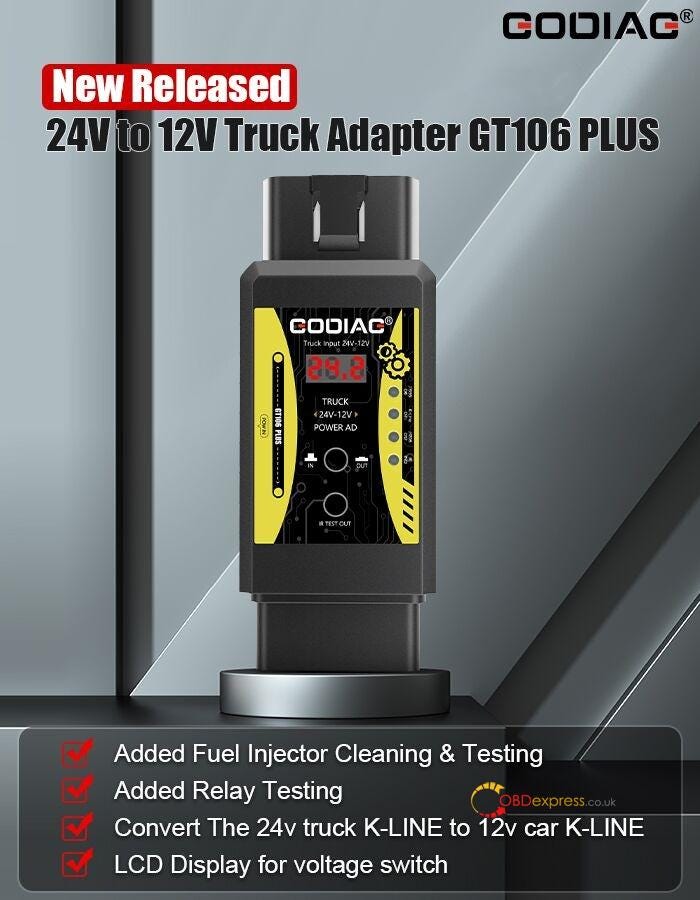
GODIAG GT106 Plus 24V to 12V Heavy Duty Truck
Adapter is the replacement of GODIAG GT106. It’s a good assistant tool for
truck/car maintenance technicians, DIY maintenance personnel. The reason is that
it not only can work with Launch 12V vehicle equipment for HD truck diagnosis,
but also supports fuel injector cleaning and relay test for cars and
trucks.
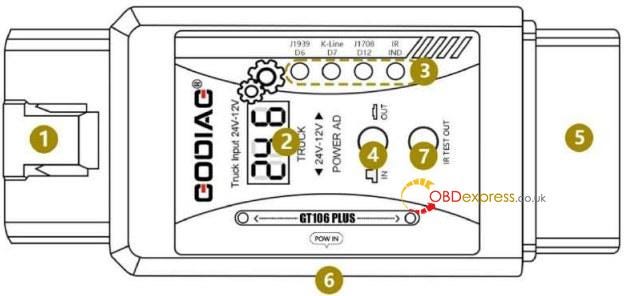
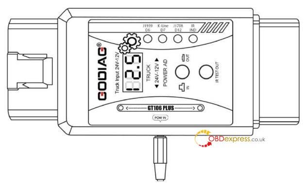
GODIAG GT106 Plus Adapter Hardware Display:
(1) OBD2 male — used to connect to the 24V truck OBD2 diagnostic
interface.
(2) Display input and output voltage.
(3) Pow — power indicator CANH/J1939 (PIN6), J1708 (PIN12), K-line (PIN7)
signal
communication indicator. Used to determine whether a device or vehicle is
communicating.
(4) Display input and output voltage function switch button.
(5) OBD2 female — used to connect diagnostic equipment.
(6) DC power input interface.
(7) Injector/relay test output interface.
How to use GODIAG GT106
Plus?
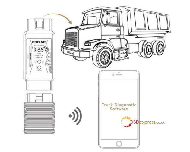
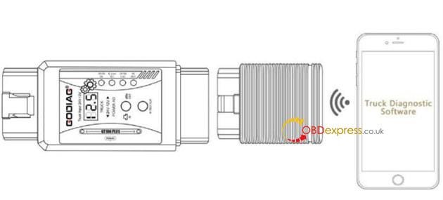
1.Convert the truck diagnostic interface 24V into 12.5V:
Convert the 24V power of the truck diagnostic interface into DC12.5V and
supply it to the 12V diagnostic equipment with truck diagnostic software, so as
to protect the 12V diagnostic equipment. 12.5V is to simulate the voltage after
the vehicle is started, which can ensure that the 12V diagnostic equipment
software can normally recognize the voltage after the vehicle is started. 【Some
diagnostic software will alarm or stop the diagnosis if it recognizes that the
starting voltage of the vehicle is lower than normal.】
2.Convert 24V truck K-Line signal to 12V K-Line signal:
The 12V diagnostic equipment 7PIN K-Line communication will be burned by the
24V K-line signal of the truck without step-down conversion. GODIAG GT106 PLUS 24V TO 12V OBD2 Scanner For
Heavy Duty Truck Adapter can convert the truck’s 24V K-line voltage signal into
12V K-line signal in order to protect the 12V diagnostic equipment 7PIN K-Line
communication from being burned by 24V.
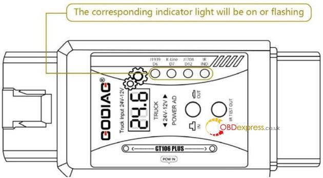
3.Communication indication function:
When CANH/J1939 (PIN6), J1708 (PIN12), K-line (PIN7) has signal communication
such as diagnostic programming, the corresponding indicator light will light up
or flash. It can display the current status of communication between the
diagnostic equipment and the vehicle.
If you do not connect the car and only connect the diagnostic equipment for
software communication signal test, you can judge whether the communication of
the diagnostic equipment is normal.
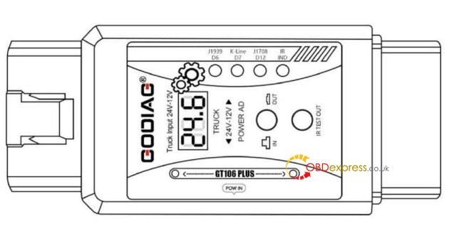
- Input voltage display function:
The display voltage function displays the currently connected vehicle OBD2
diagnostic interface voltage of 24V when the function switch button is popped
up. It can be used to monitor the current vehicle diagnostic interface voltage.
If the voltage is found to be abnormal, the operation of the vehicle can be
stopped.
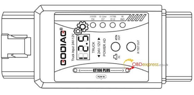
- Output voltage display function:
When the function switch button is pressed down, the voltage display shows
that the voltage of the OBD2 diagnostic output interface after the current
conversion is 12.5V.
It can be used for equipment self-test before use to ensure that the
conversion voltage is normal, which can better protect the 12V diagnostic
equipment.
- DC power interface input function
The DC power input port can be connected to the vehicle power supply, and can
also be connected to the power supply in the office. The power supply must be
higher than 13V to output normal 12.5V.
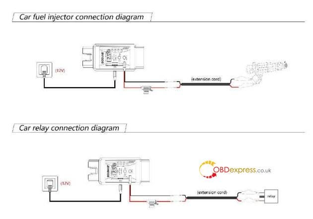
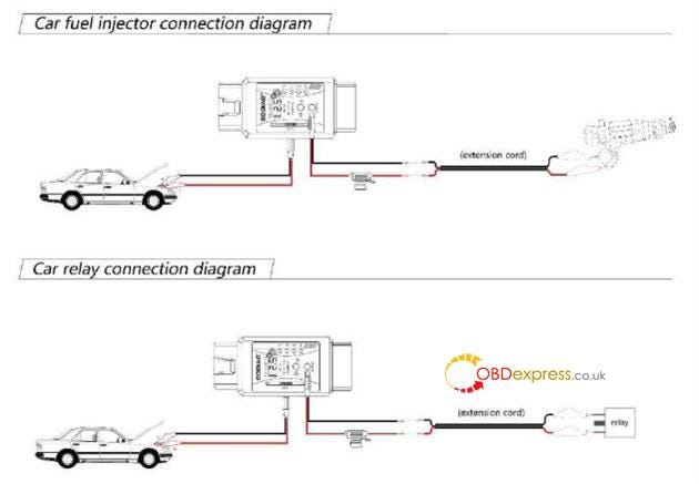
- 12V relay, fuel injector test function
Relay or injector test steps: Connect 12V DC power from the POW IN port.
Connect the fuel injector or relay according to the connection diagram, after
connecting, connect to the IR TEST OUT interface. If the relay or fuel injector
is activated, it can be judged that the tested accessory is normal.
(Note: When working, the POW IN interface needs to be connected to a DC 12V
3A power supply. Please refer to the connection diagram for how to connect the
car battery.
Relay or injector test connection line, be sure to connect the line we
provide with the fuse box. Since the power of the fuel injector is large, the
diagnostic interface is not suitable for testing high-power relay / fuel
injectors, so this device shields the diagnostic interface for relay / fuel
injector testing.)
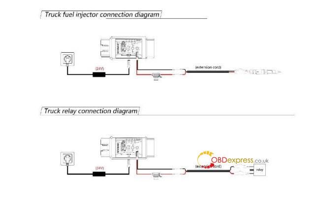
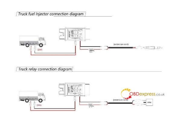
- 24V relay fuel injector test function
24V relay or injector test steps: Connect 24V DC power from the POW IN
port.
Connect the fuel injector or relay according to the connection diagram. After
connecting, connect to the IR TEST OUT interface. If the relay or fuel injector
is activated, it can be judged that the tested accessory is normal.
(Note: When working, the POW IN interface needs to be connected to a DC 24V
8A power supply. Please refer to the connection diagram for how to connect the
truck battery. Relay or injector test connection line, be sure to connect the
line we provide with the fuse box. Since the truck fuel injector has high power,
the diagnostic interface is not suitable for testing high-power relay / fuel
injectors, so this device shields the diagnostic interface for relay / fuel
injector testing.)
Videos reference:
- GODIAG GT106 PLUS Injector Testing and Cleaning
https://youtu.be/Flk1xXvaDXo
2.GODIAG GT106 PLUS Make relay, injector extension cable and
test
https://youtu.be/BDBVu0BhfOE
3.GODIAG GT106 PLUS Relay Test
https://youtu.be/tLTGMxGMqMw
4.GODIAG GT106 PLUS Voltage Conversion K-Line
https://youtu.be/7ljkyOMlZAc
5.GODIAG GT106 PLUS with GT327 diagnose Truck K-Line
https://youtu.be/VlxWc7GJulc
- GODIAG GT106 PLUS with GT327 diagnose truck ECU Bosch
EDC17CV54
https://youtu.be/p_9qCLyVMT0
- GODIAG GT106 PLUS with LAUNCH Bluetooth interface diagnose
truck
https://youtu.be/B0k13a63NDY