Here share the solution to resolve PCMTuner cannot work on bench mode, and also provide the PCMTuner Module 58/61/71 wiring diagrams for users to quickly view the wiring diagram offline without network, and for some users who only have our PCMTuner Smart Dongle as well.
PART 1: PCMTuner Bench Not Working Solution
The possible causes:
The corresponding solutions:
1. Make sure the device and ECU connection via bench cable is proper.
2. Select the correct protocol (ECU model) in pcmflash software when reading or writing ECU.
3. Do not plug in a separate 12V when you use OBD for power supply,
otherwise, it will cause the device transistor or step-down chip to
burn.
MUST USE PCMtuner professional power supply!
If you use your own lab power and voltage regulator, you cannot know how device power works, and just adjust the voltage to 13.5 or whatever you think will cause the whole triode to burn out.
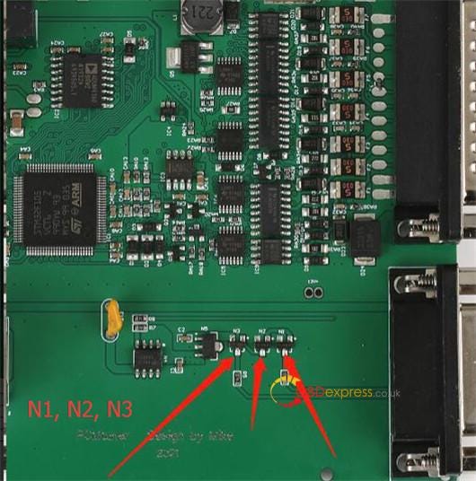
If the PCMTuner transistors are burnt, you need to replace transistors.
The transistors need to be replaced:
- N1 transistor: with MMUN2113LT1G
- N2, N3 transistor: with MMUN2211LT1G
Check the corresponding positions marked below:
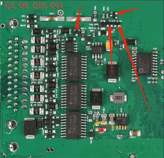
- Q3, Q9, Q10, Q11 transistor: with MMBT2222A-7-F
Check the corresponding positions marked below:
PART 2: PCMTuner Module 58/61/71 Wiring Diagram
Free download PCMTuner 58, 61, 71 protocols instruction
PCMTuner Module 58
Temic DSG/CVT
Function
DQ200MQB/G2 (0CW)
DQ250MQB (0D9)
Reading, writing, checksum correction
VL381/DL382 (0AW/0CK)
DL501/G2 (0B5)
DQ200 (0AM)
DQ250E/F (02E)
VL300/V30 (01J/0AN)
Writing, checksum correction
DQ200/MQB/G2 Boot (EEPROM)
DQ250E/F/MQB Boot (EEPROM)
DL501/G2 Boot (EEPROM)
VL381 Boot (EEPROM)
DL382 Boot (EEPROM)
Honda UDCT Boot (Continental TC1782/EEPROM)
Reading, writing
DQ200/MQB/G2 Boot (MICRO)
DQ250E/F/MQB Boot (MICRO)
VL381 Boot (MICRO)
DL501/G2 Boot (MICRO)
DQ500 (0BH/0BT)
VL300/V30 BSL (FLASH)
VL300/V30 BSL (EEPROM)
DQ250C (02E)
DL382 Boot (MICRO)
Honda UDCT Boot (Continental TC1782/MICRO)
Reading, writing, checksum correction.
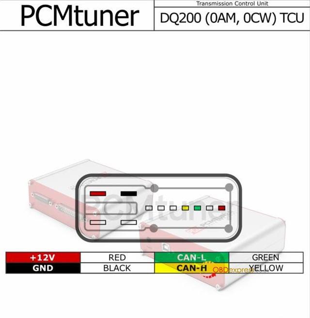
VAG DQ200 (0AM, 0CW) TCU
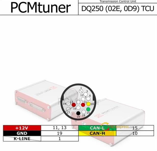
VAG DQ250 (02E, 0D9) TCU
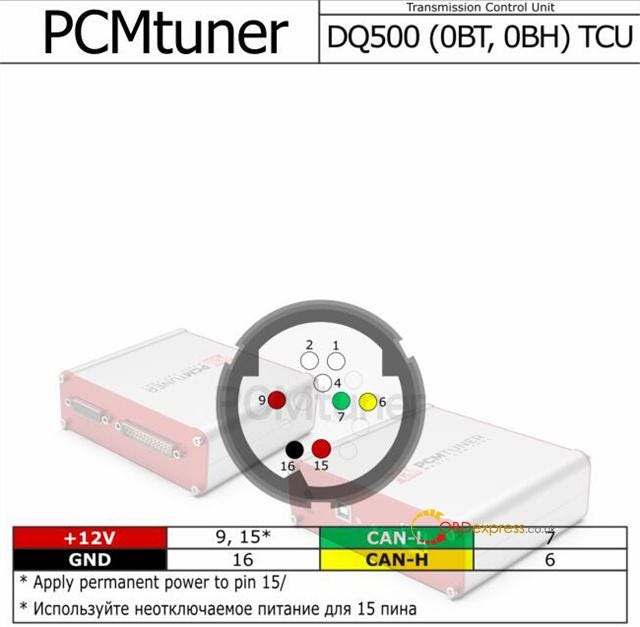
VAG DQ500 (0BT, 0BH) TCU
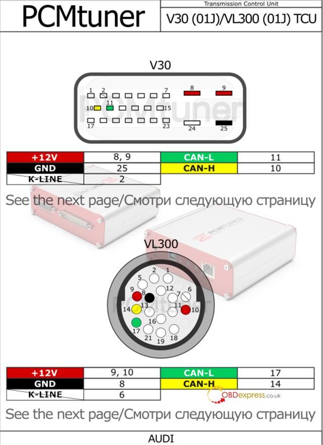
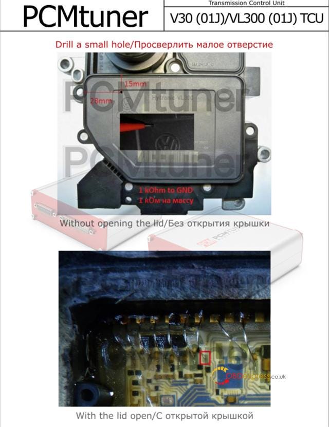
Audi V30 (01J)/VL300 (01J) TCU
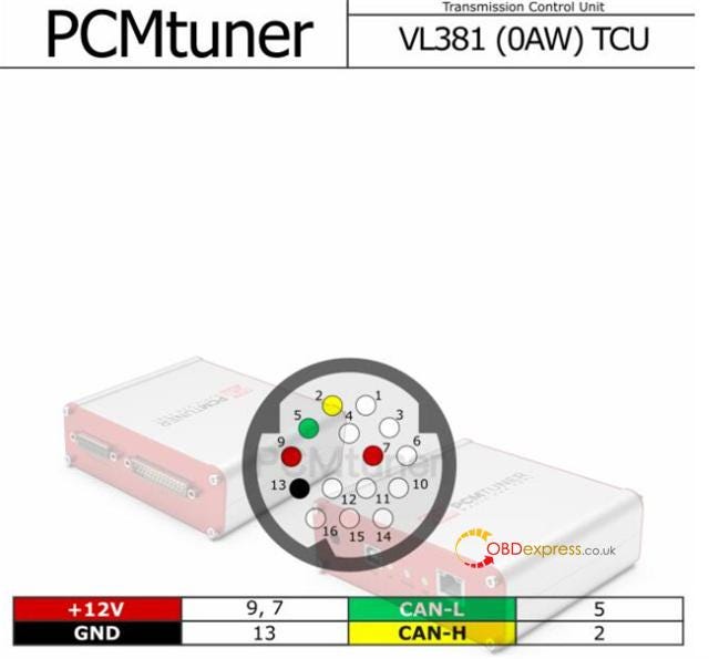
Audi VL381 (0AW) TCU
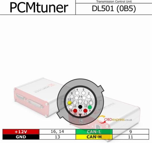
Audi DL501 (0B5) TCU
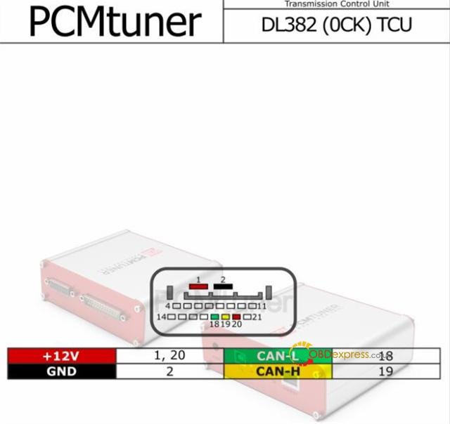
Audi DL382 (0CK) TCU
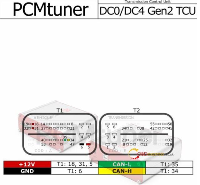
Renault DC0/DC4 Gen2 TCU
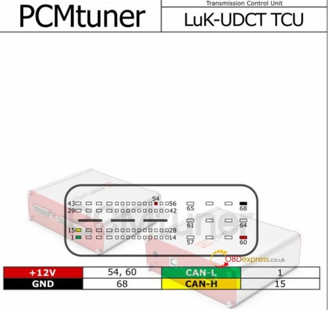
Honda LuK-UDCT TCU
PCMTuner Module 61
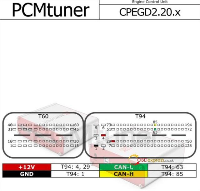
Kia Hyundai CPGDSH/CPEGD
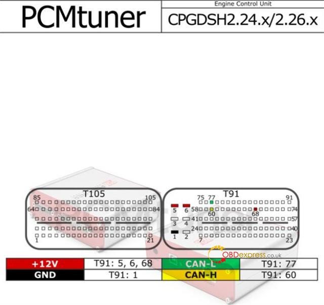
1.6L (CPGDSH2.24.1/CPEGD2.20.1/UDS
Reading, writing, checksum correction.
1.4T, 1.6L (CPEGD2.20.3/CPEGD2.20.4/UDS) — requires a direct connection to the ECU
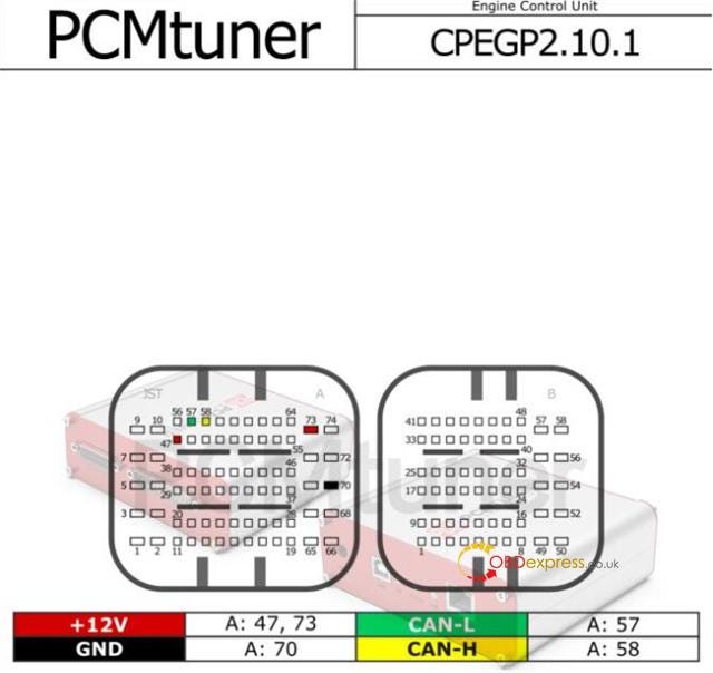
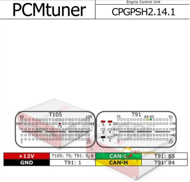
1.0L, 1.2L (CPEGP2.10.1/CPGPSH2.14.1/UDS)
Reading, writing, checksum correction, unlocking
CPEGD2.20.x
CPEGP 2.10.1
CPGDSH2.24.x/2.26.x
CPGPSH2.14.1
PCMTuner module 71
PCMTuner Bosch MEDC17 Bootloader
(direct connection to the ECU connector, Scanmatik 2 Pro, a connection cable, and a power supply are required)
MEDC17 (TC1762/1766/1792/1796) FLASH
MEDC17 (TC1724/1728/1767/1782/1784/1797) FLASH
MEDC17 (TC1791/1793) FLASH
Reading, writing, checksum correction.
MEDC17 (TC1762/1766/1792/1796) EEPROM
MEDC17 (TC1724/1728/1767/1782/1784/1797) EEPROM
MEDC17 (TC1791/1793) EEPROM
Reading, writing.
MEDC17 BSL PASSWORD
Reading.
Module 71 includes lots of ECUs and pinout diagrams.
The module 71 wiring diagrams are available in the download link above.


No comments:
Post a Comment