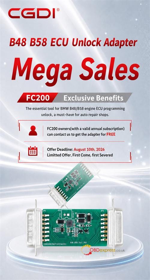
CG FC200 owners can receive a free BMW B48/B58 ECU Unlock Adapter for MG1CS024 and MG1CS201 bench setups by paying a€9 shipping charge before August 10, 2026.
Hardware Compatibility
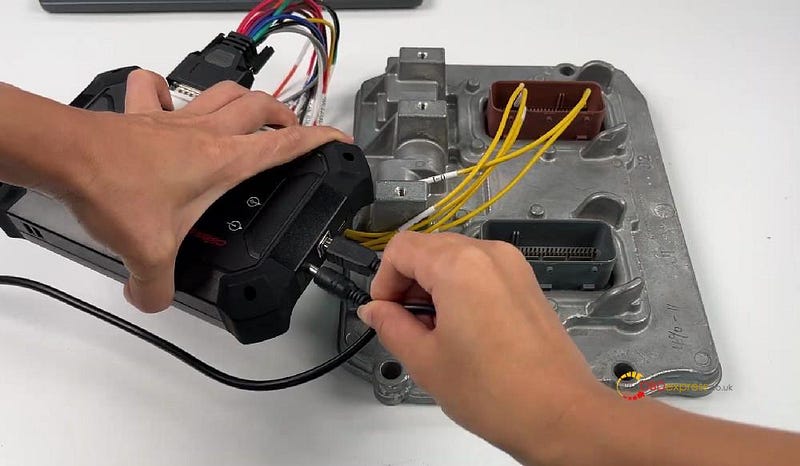
- Target Device: CG FC200 ECU Programmer
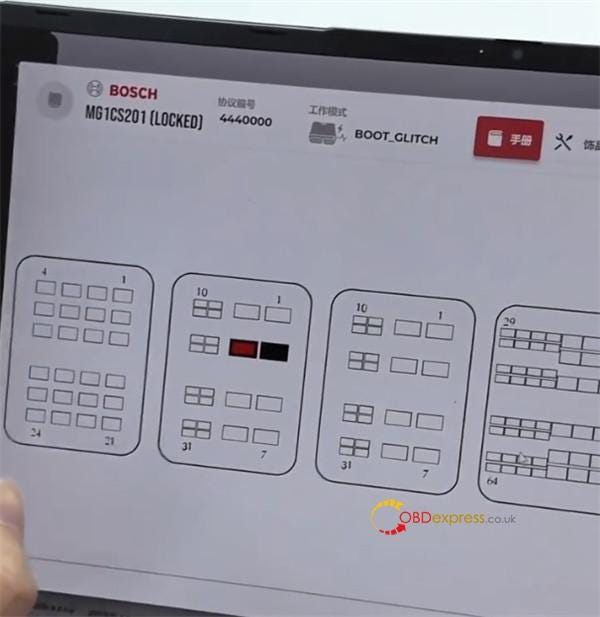
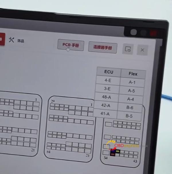
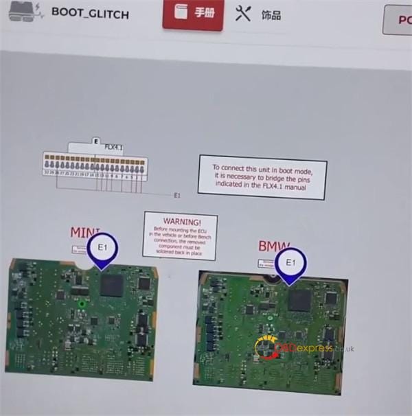
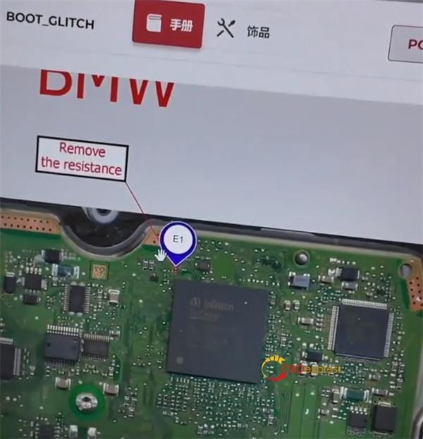
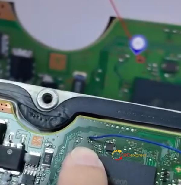
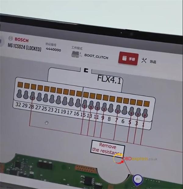
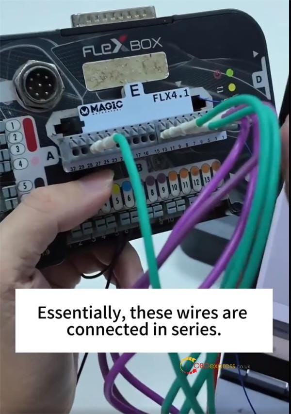
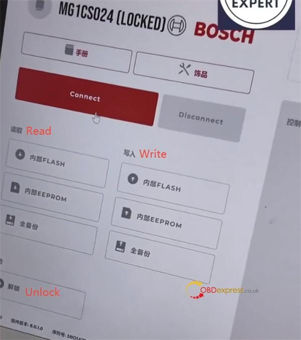
- Add-on Adapter Purpose: Bench programming unlock interface for BMW MG1CS024 & MG1CS201 ECUs (B48 & B58 engines). It is an essential tool for auto repair shops.
- Original Price: €110 (Discounted to €0 during promotion)
Everything You Need to Know Before Claiming:
1.Subscription Check: Verify that your FC200 annual subscription is current.
- If the device software license is expired, pay the FC200 Annual Renewal Fee first to restore active status.
- For the new FC200 users, please complete device activation within two weeks after the adapter promotion ends.
2.Claim Limit: 1 adapter per registered FC200 hardware ID.
3.Shipping Fee: €9 fixed logistics cost required upon order processing.
4.Expirations: Program ends on August 10, 2026. Requests submitted after this date will be processed at the standard price: €110.
5.Claim Procedure: Contact our technical support or submit your FC200 serial number online to initialize dispatch.
Contact us:
- E-Mail: Sales@OBDexpress.co.uk
- WhatsApp Business: +44 7418609676
- WhatsApp After-sales Service: +86 18750906257